|
|
Post by sparepart on Aug 8, 2021 16:20:51 GMT
So due to new fiber that we are deploying for the network, we have option to relocate our Talking house and ATU to a new location on campus.
We can devote a pair of strands for the audio, rather then routing it over the IP network with the other traffic
With that said, and almost understanding ground lead length issue:
From an FCC perspective, what happens when your transmitter is in a room atop an 80 foot tall building, and you connect the legal length ground to the steel structure (vs running a separate ground wire to the ground rod which is obviously too long per the FCC standard) ?
SP
|
|
|
|
Post by mark on Aug 9, 2021 0:25:22 GMT
|
|
Rich
Full Member
 RF Systems Engr (retired)
Posts: 112
|
Post by Rich on Aug 10, 2021 4:59:58 GMT
... From an FCC perspective, what happens when your transmitter is in a room atop an 80 foot tall building, and you connect the legal length ground to the steel structure (vs running a separate ground wire to the ground rod which is obviously too long per the FCC standard) ? SP The principles of Physics prove that the grounded steel structure of the building then becomes an active, radiating part of the "ground lead" referred to in the Rules of regulatory agencies such as the FCC. |
|
|
|
Post by Admin on Aug 10, 2021 14:05:46 GMT
"ground lead referred to in the Rules of regulatory agencies such as the FCC.".
Please provide the specific reference from the FCC regulations for those who don't know.
|
|
Rich
Full Member
RF Systems Engr (retired)
Posts: 112
|
Post by Rich on Aug 11, 2021 5:48:36 GMT
"ground lead referred to in the Rules of regulatory agencies such as the FCC.". Please provide the specific reference from the FCC regulations for those who don't know. Stated in the 'bold' text below:
U. S. Code of Federal Regulations
Title 47 - Telecommunication
Volume: 1Date: 2010-10-01Original Date: 2010-10-01Title: Section 15.219 - Operation in the band 510-1705 kHz.Context: Title 47 - Telecommunication. CHAPTER I - FEDERAL COMMUNICATIONS COMMISSION. SUBCHAPTER A - GENERAL. PART 15 - RADIO FREQUENCY DEVICES. Subpart C - Intentional Radiators. - Radiated Emission Limits, Additional Provisions.
§ 15.219 Operation in the band 510-1705 kHz. (a) The total input power to the final radio frequency stage (exclusive of filament or heater power) shall not exceed 100 milliwatts. (b) The total length of the transmission line, antenna and ground lead (if used) shall not exceed 3 meters. (c) All emissions below 510 kHz or above 1705 kHz shall be attenuated at least 20 dB below the level of the unmodulated carrier. Determination of compliance with the 20 dB attenuation specification may be based on measurements at the intentional radiator's antenna output terminal unless the intentional radiator uses a permanently attached antenna, in which case compliance shall be deomonstrated by measuring the radiated emissions.
|
|
|
|
Post by Admin on Aug 12, 2021 0:23:01 GMT
Hmmm, doesn't refer to attachment to structures.
|
|
Rich
Full Member
RF Systems Engr (retired)
Posts: 112
|
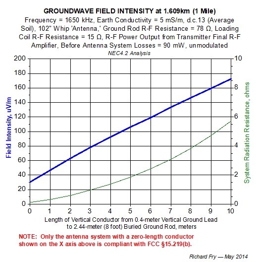
Post by Rich on Aug 12, 2021 7:45:11 GMT
Hmmm, doesn't refer to attachment to structures. But it does refer to ground.
A conducting steel frame (or water tower, flag pole, billboard, "massive ground wire" etc) projecting above the surface of the Earth provides a path for r-f current from the opposite end of a physically short "ground lead" connected to it from a transmitter to continue to flow along that structure until it reaches its electrical interface with the Earth (ground), that the structure stands upon.
This reality of Physics is illustrated in the graphic below by the increased field intensities such systems using extended-length "ground lead" paths can produce at 1 mile, with other things equal.
|
|
|
|
Post by mark on Aug 12, 2021 16:12:56 GMT
Hmmm, doesn't refer to attachment to structures. That's the problem. That makes a grey area. It's subject to what an agent thinks at his or her discretion. Is an elevated structure not connected to the earth by conductor the same as a long wire ground lead just dangling not connected to anything in the earth a ground lead? Not good if something is not clear or written in stone and an agent can decide on the scene and make the law then and there. The subject of ground leads goes on and on but at least gets some action going on the forums! |
|
|
|
Post by sparepart on Aug 13, 2021 1:47:01 GMT
Two situations: a) Our part 15 transmitter (talking house and ATU as an example) is ground mounted and connected by 14" of wire to the ground mat of a 160M amateur radio station consisting of 140 radials of at least 1/4 wavelength b) Our part 15 transmitter (talking house and ATU as an example) is connected by 14" of wire to the steel frame of the building. "a" is ok and "b" is not??
SP
|
|
|
|
Post by sparepart on Nov 30, 2021 16:24:30 GMT
§ 15.219 Operation in the band 510-1705 kHz. (a) The total input power to the final radio frequency stage (exclusive of filament or heater power) shall not exceed 100 milliwatts. (b) The total length of the transmission line, antenna and ground lead (if used) shall not exceed 3 meters. (c) All emissions below 510 kHz or above 1705 kHz shall be attenuated at least 20 dB below the level of the unmodulated carrier. Determination of compliance with the 20 dB attenuation specification may be based on measurements at the intentional radiator's antenna output terminal unless the intentional radiator uses a permanently attached antenna, in which case compliance shall be demonstrated by measuring the radiated emissions.Inserted four R-1000 GR1 standoff insulators between the Range Extender aluminum mounting bracket and the steel mounting plate, which is welded to the mounting arm. There is no electrical connection between the aluminum bracket and support structure. The ground wire is literally hanging from the ground lug and not electrically connected to anything else. TX frequency is 800 kHz, the measured combined length of the radiator and ground wire is 115 inches (2.921 meters) Covers our campus quite well and just a bit more!
SP
|
|
Rich
Full Member
RF Systems Engr (retired)
Posts: 112
|
Post by Rich on Dec 8, 2021 9:42:08 GMT
... (b) The total length of the transmission line, antenna and ground lead (if used) shall not exceed 3 meters. ...Inserted four R-1000 GR1 standoff insulators between the Range Extender aluminum mounting bracket and the steel mounting plate, which is welded to the mounting arm. There is no electrical connection between the aluminum bracket and support structure. The ground wire is literally hanging from the ground lug and not electrically connected to anything else. Could there be an unrecognized path increasing the radiating length of the installed antenna system due to common-mode r-f current flowing along the OD of the shield of the coaxial cable connecting the transmitter to its Range Extender? |
|
|
|
Post by sparepart on Dec 10, 2021 0:09:03 GMT
... (b) The total length of the transmission line, antenna and ground lead (if used) shall not exceed 3 meters. ...Inserted four R-1000 GR1 standoff insulators between the Range Extender aluminum mounting bracket and the steel mounting plate, which is welded to the mounting arm. There is no electrical connection between the aluminum bracket and support structure. The ground wire is literally hanging from the ground lug and not electrically connected to anything else. Could there be an unrecognized path increasing the radiating length of the installed antenna system due to common-mode r-f current flowing along the OD of the shield of the coaxial cable connecting the transmitter to its Range Extender? With this being an FCC approved, turn-key system, doing anything to mitagate RF on the shield would be a modification, voiding the FCC ID
SP
|
|
Rich
Full Member
RF Systems Engr (retired)
Posts: 112
|
Post by Rich on Dec 27, 2021 7:48:39 GMT
Could there be an unrecognized path increasing the radiating length of the installed antenna system due to common-mode r-f current flowing along the OD of the shield of the coaxial cable connecting the transmitter to its Range Extender? With this being an FCC approved, turn-key system, doing anything to mitagate RF on the shield would be a modification, voiding the FCC ID
SP
That is one assessment of the situation. But maybe a more accurate one is that the FCC would be unlikely to permit the operation of an unlicensed transmit system using the AM broadcast band that was functionally non-compliant with the limits contained in U.S. 47CFR Part 15.209 or Part 15.219 — even if it had received a certification number from the FCC. IOW, the applicable Part 15 Rules would prevail. |
|
|
|
Post by mark on Dec 28, 2021 1:54:20 GMT
Very interesting debates about ground leads but here's something I did that will work with the Procaster and the Rangmaster as they are both similar in design with a metal weatherproof cabinet either steel or in the case of the Procaster aluminum, and an on board tuning meter. I created an "artificial" ground inside the cabinet. Here's what I did and didn't know it would do anything but was worth a try. I have an indoor set up using a wire not the stock antenna. Procaster's stock antenna length is 104" not 3 meters as 14" is left for the ground lead if used. So I have an antenna just a little longer than 104" which is shorter than 3 meters. No ground. Also found that trying different shapes with the wire made a difference in the peaking of the meter which with a hand held signal meter verified signal coming off the antenna is related to the meter reading and the thickness of the wire changes things too. With it set up a certain way and not changing anything I did this. I disconnected the thick wire that was clipped to the circuit board ground terminal to the cabinet ground terminal on the outside. Then got some thin 24 gauge wire and connected one end to the ground lug inside and wrapped the wire around the circuit board on the sides where the board is screwed down to the cabinet 2 times and then did a two turn loop around the little tuning meter then connected the other end of the wire back to the ground lug on the circuit board. So it was a double loop with a small loop at the meter. I was surprised! All else not touched exactly like it was before there was a significant jump in the meter reading that corresponded with an equal amount of signal increase off the antenna when I did this. Nothing else was touched just the wire that I described. It is inside the cabinet and shielded so nothing is external radiating into space except the normal antenna. I even had to adjust the meter setting as per instructions with the trimmer as I was pegging the meter at the top end past the 10 and needed to see a peak. For someone not having the property to install an outdoor ground this little trick will work. No ground leads needed. Posted a picture but not best resolution to post here as it can't be more than 1 MB.  |
|